System Flow Rate
CALCULATING THE ENTIRE SYSTEM’S FLOW RATE
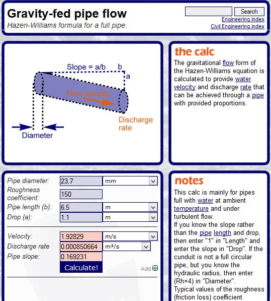
The home owner who plumbed the METHOD B example was able to calculate the length the second drop needed to generate the required flow rate by using the simple Hazen-Williams flow rate calculator linked below and the calculation for the second photo’s flow rate is further below.
http://www.calctool.org/CALC/eng/civil/hazen-williams_g
You need to change the roughness coefficient from 140 to 150 for uPVC pressure pipe.
The nominal 20 mm pressure pipe’s internal diameter is 23.7 mm, giving a volume of 0.441 litres per metre. You need to change the calculator’s setting from cm to mm if you enter 23.7.
When you enter the total head and the total friction loss of the system’s full length, the calculator’s answer is given as the velocity in metres per second (mps). To calculate litres per minute, you multiply mps x 60 x 0.441.
The example below shows the calculation for the second photo’s total friction loss figure of 6.5 metres with a 1.1 metre total head.
The 6.5 metre total friction loss includes the 3 x 90 degree elbows fitted at the bottom of the second drop. The black fitting is a 90° elbow that directs the water downwards, it is recommended to not have the high velocity inflow blasting against the downpipe’s wall. Most drops are fitted to the downpipe at a 45° angle.
As shown, the velocity of 1.928 metres per second x 60 x 0.441 = 51 litres per minute for the photo 2 installation.


